

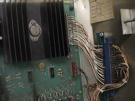
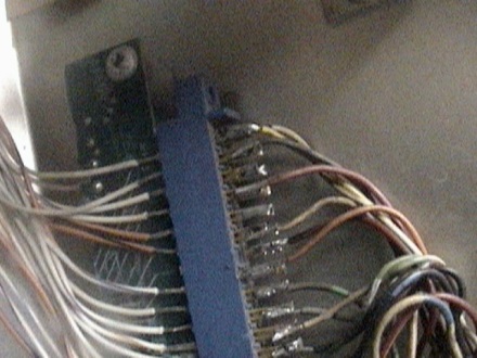

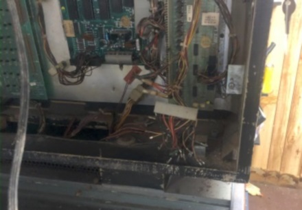
The four pics above show the ingenious hack that the operator did to connect the solenoid driver board. He directly soldered wires to the J3 connector and then soldered those to a Gottlieb style edge connector. Then the edge connector was screwed into the side of the head and the wiring harness could connect there. He must not have had the normal .100 25 pin connector available and used what he had. The second two pictures are where I have cut the wires awaiting installing the proper style connector.
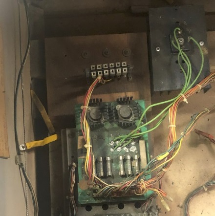
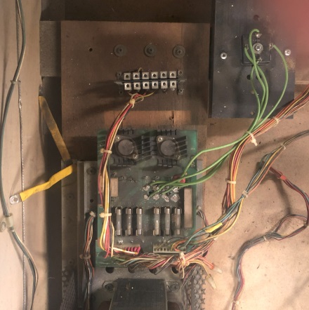
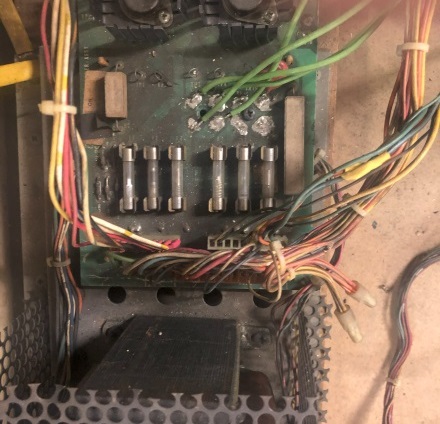
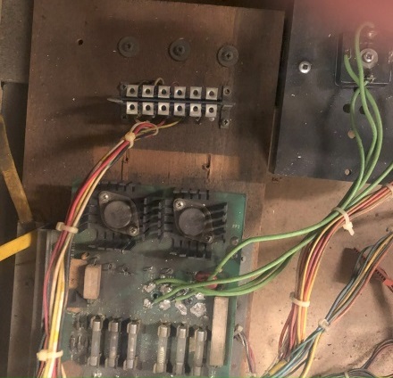
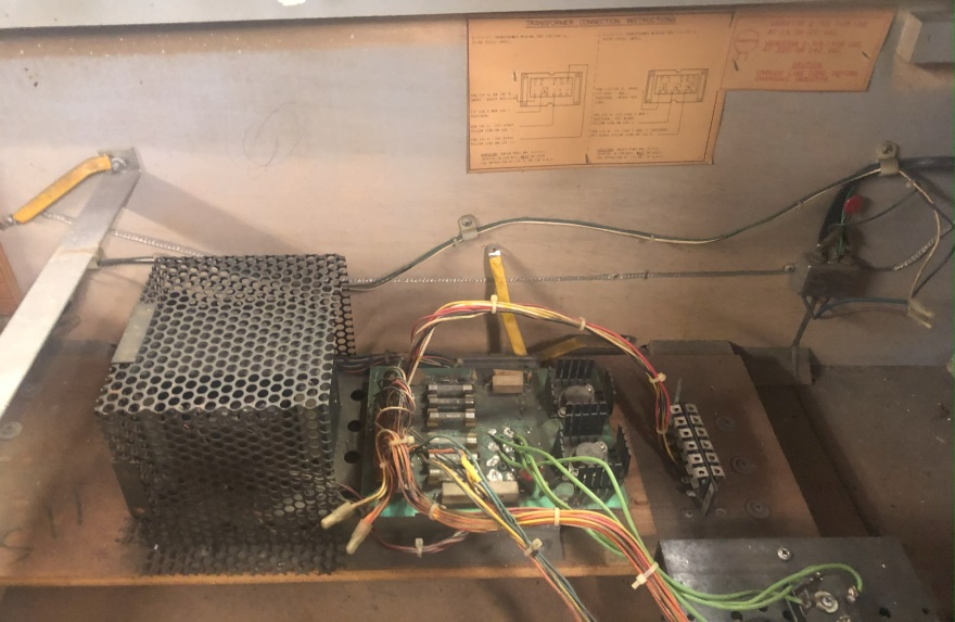
Above is the rectifier (power) board. Several hacks were made to this board. First, they had moved the bridge rectifiers off of the board onto a separate metal plate and then directly solder the wires to the board and the bridge leads. Second, the J3 connector wires were directly soldered to the pins. Third, the J1 wires were directly soldered to the pin and then connector to an old EM style connector which was then attached next to the rectifier board. This allowed the operator to disconnect J1. Again, an unusual but workable hack.
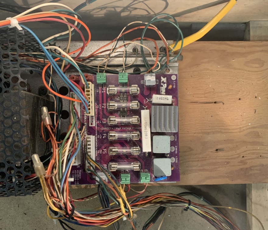
Above is the new XPin power board that I installed as a replacement. Note that no soldering is required. You just strip the wires and insert into the proper locations (green housings at edges of the board). The board comes with good instructions on how to install and wire it. The main thing is that since it is backward compatible with older boards, you need to make sure that connector J2 is correct for your game as it could be an eight or nine pin housing.