Testing Bally Lamps
Below is a step-by-step process for fixing non-working lamps on a Bally game. Bally lamp issues are USUALLY pretty straight forward and easy to diagnose and fix because of how their lamps work. They did not use a lamp matrix like Williams. Rather, each lamp is a discreet circuit so it is fairly easy to figure out what is wrong. Below will give you a list of what could be wrong and then the steps for diagnosing each of the possible problems. After that, I will give some miscellaneous notes. Note that you probably won’t need to do all of these steps. This is what I do when I get an old game that has several non-working lamps. I’ve found that on an old game that hasn’t been used in a while the lamps can have multiple issues causing them not to work. So, I fix it by doing the following. Again, use only the steps that you actually need. This is just a comprehensive way to track down lamp issues.
Quick Synopsis of How the Lamps Work
- Power (6 vdc) comes to the playfield from the Power board (Fuse F1 and bridge BR1) via the bare ground wire that goes from lamp to lamp. Basically 7.8 vac comes from transformer through fuse F1 (10 amp on pre-Xenon and 20 amp post-Xenon) to bridge rectifier (BR1) which converts this to 5.4 vdc which goes to the playfield.
- Each lamp has a discreet wire that goes from the lamp to the lamp board.
- Signals from the MPU board are sent to the lamp board (MPU J1:11-19 to Lamp J4:4-11, 13-17)
- A decoder chip on the lamp board processes these signals and sends signals to the appropriate transistors.
- The transistor grounds the circuit and turns the lamp on.
Basic List of Possible Lamp Issues
Here is a basic list of what could be wrong. Remember, you might have multiple issues with a lamp especially on older games or ones that have been in storage for a while.
- Bad bulb.
- Bad socket.
- Bad ground wire.
- Bad wire from the light board to the lamp.
- Bad connector on the light board.
- J1, J3 go to the playfield.
- J2 goes to the backbox.
- Bad pin on the light board.
- Bad transistor on the light board.
- Bad decoder chip on the light board
- Bad connector J4:4-11, 13-17 on lamp board. This is where the logic signals enter the lamp board from the MPU board.
- Bad pins J4:4-11, 13-17 (see above).
- Bad connector on MPU J1:11-19 (this is where the signals for the lamps are sent to the lamp board).
- Bad pins on MPU J1:11-19.
Testing Techniques
- Start by putting the game into the lamp test mode by pushing the red button on the front door one time. This should cause all of the MPU controlled switched lamps to blink on and off. Create a table and in the far left column write down all of the non-working lamps. Then create columns for connector/pin, transistor number, bulb, socket, wiring, connector, pins, transistor, decoder, MPU signal.
- Twist, remove and then replace the bulb into the socket to see if the bulb will light. Often the old sockets get crud build up, oxidation, and material deterioration causing the bulb to not work. Often you can get a bulb to work by doing this. Note that often if the bulb works after twisting, pushing, and prodding on the socket, it may still give you problems. It isn’t actually “fixed” permanently. This means the socket has issues. So, this rules out anything else being the cause. You can mark your chart that the issue is the socket. Your options at this point are:
- Replace the socket
- Sand, file, clean the socket which can often get rid of some of the crud causing the socket to not make a good connection
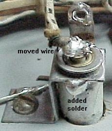
- “Hot wire” the socket. This means adding some solder to the base of the socket directly connecting the wired base to the socket. Then solder the wire directly to the socket base. In the right pane is a picture of this from Clay Harrel’s website. You are soldering two places, the socket edge and the wire to the socket base.
- Change the bulb by swapping it with a known good bulb. If the bulb in the bad socket works in the new socket and the working bulb from good socket does not work in the non-working socket, then you at least know the problem isn’t the bulb itself. This is basically a check of the bulb. You can now mark the bulb column in your chart.
- Check the socket by jumping an alligator clipped wire from one of the working lamp wire leads to the wire lead on the non-working lamp. If the lamp works now, then you know the socket and bulb work. So, the problem is downstream in the wiring, connectors, or boards. Mark the socket for this bulb on your chart accordingly.
- If you suspect that the common bare ground wire might be the problem, you may need to jump a wire from the ground wire on a working lamp to the non-working lamp. Sometimes due to the shaking that takes place, the ground wire can work loose from the base of the socket.
- Another socket test I use it to take a spare WORKING socket with a bulb in it. I then jump a wire from the ground wire to the base of that socket and then jump a wire from the non-working lamp to the wired tip on my test lamp. If the test lamp works, then I know that the problem is with the socket or bulb. Since the spare lamp works when put in the circuit for a particular lamp, it rules out the wiring and board issues.
- Once I’ve eliminated the lamp and socket as the culprit, I go back to my chart of bad lamps. Hopefully, some of them have been fixed. For the ones remaining, I go to the schematic and write down the transistor and connector for each particular lamp. To find this, look on the right side of the lamp driver schematics and find the light description (ex. Bonus 9k). Then see which connector and pin number the lamp uses. Follow the line from the connector to the Q number of the schematics. The Q number is the transistor number and corresponds to that transistor on the lamp board. If you want, you can also trace the transistor back to the decoder chip that drives it. To be honest, I’ve never had one of these go bad on any game I have worked on, but this might be the issue. Now you have a chart with the non-working lamps, its corresponding transistor, and connector and pin number and the decoder chip.
- This next test is the next logical test though I don’t always do it next. This test is for checking the wiring itself and this is usually NOT the problem. So I don’t do this step unless I am having trouble and I want to eliminate the wiring as a possibility. I turn the game off and with my DMM test the continuity from the lamp tip to the lamp’s connector. The .100 connectors are really small so you may have to attach a small wire to the end of one of the leads of your DMM to insert into the connector to check the continuity. If there is no continuity, then I may have a break in the wire somewhere. Again, this is very rare. I’ve had this happen to me twice. Once, a wire in the middle of a zip-tied bundle had somehow broken (I’m still trying to figure out how it happened) and then on the Supersonic, I had rats eat through multiple wires and I missed a wire when soldering the whole group back together.
- Re-do the pins on the lamp board. Again, try some of the tests below first, but we are doing this in logical order. Another note, I tend to do every test I can with the board in the game first. I then go to tests that require the board to be removed from the game regardless of the logical order.
- Re-do the connectors. Re-crimping and re-doing the connectors can often fix issues. Connectors and pins are a common problem for old games especially if it has been stored for a period of time. The pins and/or connectors can oxidize and prevent the signal from making it to the lamp.
- Transistor test game on:
- Put the game in display test (not lamp test) by pushing the red diagnostic button on the coin door twice. The displays will cycle through the numbers 0-9.
- Take an alligator clip test wire and attach one end to ground. You can use one of the ground test points on a board or the grounded braid wire that runs throughout the cabinet and backbox.
- Per Clay, touch the other end of the test lead to the ANODE (A) of the SCR in question. On the larger MCR106, the metal face or metal tab is the anode. On the smaller 2N5060 SCRs, it's the lower right leg. To make sure, the pinout for the SCRs is silk screened on the board. Look for the lead marked "A".
- If the lamp does NOT light when the anode is grounded, the problem is NOT on the lamp driver board. Most likely you have a wiring problem, a bad lamp socket, or a bad bulb.
- If the lamp lights, then the transistor is bad and needs to be replaced.
- Transistor test #2 with game on (per Clay):
- With the game on and in score display test mode, connect one end of an alligator jumper to Lamp Driver board TP3 (goes to R70 2k ohms).
- Connect the other end of the alligator jumper to the GATE (G) of the SCR in question. On the larger MCR106, this is the left leg. On the smaller 2N5060, this is the right side (center) leg. The G will be marked on the board.
- The lamp in question should light.
- If the lamp does not light, the transistor is probably bad.
- Transistor test game off:
- With the board out of the game and on your bench, test the appropriate transistors like below. Note that the big transistor are actually SCRs but I just use the word transistor to cover both the big and little ones on the board. This is per Clay again.
- For the “Big” SCRs, put the black lead of your meter on the outside "cathode" leg (labeled "C") of the SCR.
- Put the red lead of your meter on the outside "gate" leg (labeled "G") of the SCR. Your meter should read .4 to .6 volts.
- Swap the meter leads. Now the meter should read 1.4 to 1.6 volts.
- Note that I have at times had good transistors read slightly outside this range and a bad one read close to this. So I usually do multiple tests to make sure.
- For the “smaller” transistors put the black lead of your meter on the "cathode" leg (labeled "C").
- Put the red lead of your meter on the center "gate" leg (labeled "G"). Your meter should read .4 to .6 volts.
- Swap the meter leads. Now the meter should read 1.4 to 1.6 volts.
- Test the decoder chip: I don’t actually test it. If several lamps don’t work that lead back to a single decoder chip then replace it. They are pretty cheap. I’ve never had one go bad but it does happen.
- Re-do pins and connectors on the MPU J1 and Lamp J4. This is where the signal from the MPU originates and is sent to the lamp board. If a single lamp is not working, you can eliminate this. This issue does crop up though.
More Quick Thoughts
- If a lamp is stuck on, then it is usually a shorted transistor.
- If multiple lamps are not working and they all go to the same decoder chip on the light board, then you might have a bad decoder chip.
- Without going into details, if multiple lamps don’t work but they can all be traced to the same data lines (AD0-3 or PD0-3) then the issue could be the pins on the MPU (J1) or light board (J4). You can use your schematics to figure out if this might be the problem.
- Some games use a lamp expander board. Most of the diagnosing techniques above will work on that board as well. You just have to know that it exists and is a possibility. Make sure its pins and connector are in good shape.
- Clay points out that a bad coin door switch that is grounded to the door can also wreak havoc. I’ve never had that happen but if you want to eliminate this as a possibility remove MPU J3 which will take the coin door switches out of the equation.