Machine Statistics
Production Date: August 1977
Production Run: 12,820 units
Design: Gary Gayton
Artwork: Kevin O'Connor
The Game Synopsis/History
Strikes and Spares was one of the first generation solid state games produced by Bally. It used the –17 board and had chimes for sound. The start-up tune is known in professional horseracing as "The Call to the Post." Odd that they would use a theme used in horse racing for a bowling themed game.
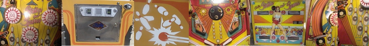
Strikes and Spares is probably best known for the artwork on the backglass. This backglass has become one of the more collectable backglasses around. Besides the more obvious attraction of the backglass, there are also a couple of humorous drawings on it. Also, if you will look at the score card surrounding the second player display, you will see where artist Kevin O’Connor signed his name.
In my lot of 19 games that I bought out of Canada to restore, there were two Strikes and Spares. This particular one was the worse of the two.
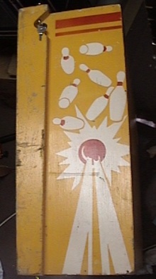
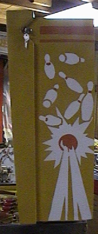
Of all the games I have restored, this one was probably the most rewarding because this game was in the worst overall shape of any game I have ever attempted. The cabinet was a disaster. While it may not have looked as bad as my Flash Gordon, it was in worse structural condition. Besides the obvious scratches and dings on the outside, the cabinet had several gouges in the wood frame, a broken brace, and a couple of corner pieces that had separated.
As for the electronics, the power board was possessed. It took a couple of nights and upgrades to get it working. The driver board and light board needed several transistors replaced. Only two displays worked. The one consolation was that the MPU worked after getting the power board going. The playfield was also a disaster. I did get a spare playfield that was in average condition and did a playfield swap. The replacement playfield is average at best, but it is significantly better than the original. The backglass was the one redeeming piece of the game. It was in excellent condition.
Section 1: Electronics
Problem #1: Connectors on Rectifier board.
The arcade that previously owned the game had soldered the wires directly to the pins on the power board. They then cut the wires and installed a makeshift connector housing to each end of the wires so that they could disconnect the wires from the power board.
I removed the power board and replaced all of the pins. I then rebuilt the connectors with the proper connectors. I did make one mistake and built one of the connectors upside down. It doesn’t affect how well it works but it could confuse someone. Therefore, I wrote with permanent marker which side was up on all the connectors and made sure they all had their “key” plugs installed. This should prevent any one from accidentally installing the connectors upside down. I probably should have just re-did the connector but I was lazy.
Problem #2: I upgraded the power supply board.
I upgraded the power supply board by doing some of the modifications suggested on Clay’s site. I replaced the 8 amp bridge rectifiers with the heftier 25 amp bridges. I also replaced the header pins and re-did the housing connectors.
This power board gave me fits. First, a couple of the wires from the transformer had pulled loose. Soldering them back on wasn’t a problem except that a couple of the pads were in bad shape. After installing the bridge rectifiers, I still couldn’t get the general illumination lamps on the playfield to work or the switched lamps.
The general illumination test point on the rectifier board tested OK. This meant that the problem wasn’t with the bridge rectifiers. Also, the GI lights on the backbox worked. So, the problem had to do with the playfield GI only. First, I checked the continuity from the connectors to the playfield and found that it was OK. Ultimately, the problem had to do with the ground pins on the rectifier board. The trace was damaged so I had to jump a wire from the pins and solder it to the ground plane on the board. This fixed the general illumination problem but not the switched illumination.
The switched illumination test point did not test correctly. This meant that the bridge was bad. However, the bridge tested fine. Also, when I tested the continuity through the bridge it tested OK also. In fact, in the board, this bridge tested just like the other two bridges which did work. I removed this bridge and tested it out of the board and it tested good. So, I reinstalled it and still had the same results. To make a long explanation short, the problem was that the pads were bad and not making contact with the traces. However, when I tested the bridge, I put enough pressure on the leads to force them to make contact, thus making it look like everything was OK. I finally resoldered each of the leads making sure that the leads contacted the traces. I also put jumper wires from two of the leads to make sure that the connection worked. This fixed my problem.